
Relocating your battery to the front and rewiring the power source for the car:
After working in the engine bay for quite some time during my 20V Silvertop swap, I really noticed how “in the way” the stock battery location is. Not only does the battery take of valuable physical space in the engine bay, but the battery mounting bracket system is quite large. The whole forward driver side section of the engine bay is effectively filled by the battery. With a goal to free up this space for a possible intercooler addition, I decided to perform the popular frunk battery relocation modification. This involves mounting the battery in the front trunk of the car, and running a power wire from the battery to the engine harness in the rear. During the process, I decided to run additional power wires and modulate my power distribution for other planned projects.
Step 1: plan the system
The first step is to plan and outline the new system, sketching out what you need and where everything will go is a good idea. Supplies will need to be purchased for this swap and thinking about them beforehand simplifies the task of getting everything together. In my proposed plan, the new battery is mounted in the front, a large 1/0 gauge battery cable is regulated by a 150A re-settable fuse and then runs through the cabin to the rear and is connected to a power distribution block in the engine bay. This power block is responsible for providing power to any components at the rear of the car, most notably the engine harness, but it also has ports for any other future peripherals. A second power wire from the battery of 8 gauge size is regulated by an 80A re-settable fuse and then runs through the firewall and is connected to a power distribution block in the cabin. This block is responsible for powering any components in the cabin, most notably my new amplifier and gauges. A final power wire from the battery (12 gauge) runs to the front of the car and powers my new Hella Fog lights. The final step is to ground everything appropriately. The battery is grounded to two points in the front, and the engine is grounded to three points in the rear.


Step 2: Battery mounting
With the battery mounted in the front a good solid mounting system needs to be devised. The last thing you would want is a heavy battery shifting around during driving. I liked the stock method of securing the battery, which consists of creating a solid platform, and clamping a bar down across the top of the battery. I decided that I would weld in a new platform, and use the stock J-hook clamping rods.
First I needed to find an appropriate location for the new battery in the frunk. I made a cutout of my battery profile and placed it in several locations to see how it looked. I should also mention that I decided to upgrade my battery and purchased an Odyssey PC680 battery, which is both lighter and smaller than the OEM style lead-acid. I liked the passenger side as a mounting location for the battery, I figured I could create a fairly simple mounting platform using the natural ledge that runs around the frunk cavity.


With this location for the battery decided on, the next step was the construct the platform. First you need to grind away the paint to bare metal in areas which you will weld. I cut some angle steel to create the platform, and a steel bar for the support. Using my MIG welder I tacked everything in, checked it looked ok, and then welded it in completely. The welds didn’t come out too pretty, but the mount is secure. Using the OEM J-hooks, a small hole was cut into the frunk wall behind the battery, and a small hole was cut into the angle-bar at the front of the battery. A shiny new aluminum battery bar was used to securely clamp down the battery.


The new setup was then primed and painted. I used a color-matched paint from AutomotiveTouchup. For the base, I cut out a small piece of rubber foam, something similar to what you use to line drawers of your toolbox. The finished product is both solid and looks good.


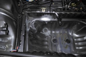
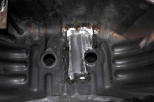
The next step was to create a mounting bracket for the fuses. It’s a good idea to keep the fuses as close to the battery as possible, so I decided to weld in a bracket mount right beside the battery. On the stock MR2 this is where the spare-tire mount is located. I cut the mount free and pulled it off. As you can see, the removal left a few small holes to fill with the welder. This area was then pounded flat with a hammer (for the angled bracket mount) and ground clean. In addition, I had some rust forming at the base of my frunk, I had originally performed a quick patch using fiberglass, but the repair was only temporary. I decided to fix the problem properly and cut/ground out all the rusted metal.


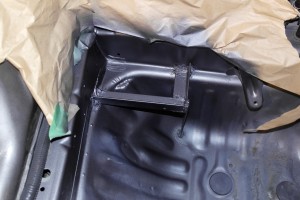
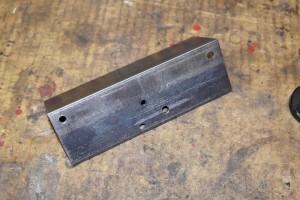
The fuse bracket was made from some 1.5 inch 1/8 thick angle steel. I drilled some holes for the fuses with the drill press at work. I then welded it in place, again the weld wasn’t pretty but it’s more than secure.


To fix the hole in the floor, I cut and bent and piece of 22 gauge steel sheet. Tack welded the corners in place, and then finished up the weld. After this was complete, I primed everything and then painted it all the factory silver grey.


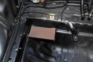
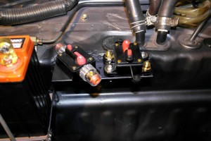
The fuses were mounted in place (150A and 80A reset-able fuses are on top, the relay for the fog lights is located below). Next the wiring.

Relocating your battery to the front and rewiring the power source for the car:
After working in the engine bay for quite some time during my 20V Silvertop swap, I really noticed how “in the way” the stock battery location is. Not only does the battery take of valuable physical space in the engine bay, but the battery mounting bracket system is quite large. The whole forward driver side section of the engine bay is effectively filled by the battery. With a goal to free up this space for a possible intercooler addition, I decided to perform the popular frunk battery relocation modification. This involves mounting the battery in the front trunk of the car, and running a power wire from the battery to the engine harness in the rear. During the process, I decided to run additional power wires and modulate my power distribution for other planned projects.
Step 1: plan the system
The first step is to plan and outline the new system, sketching out what you need and where everything will go is a good idea. Supplies will need to be purchased for this swap and thinking about them beforehand simplifies the task of getting everything together. In my proposed plan, the new battery is mounted in the front, a large 1/0 gauge battery cable is regulated by a 150A re-settable fuse and then runs through the cabin to the rear and is connected to a power distribution block in the engine bay. This power block is responsible for providing power to any components at the rear of the car, most notably the engine harness, but it also has ports for any other future peripherals. A second power wire from the battery of 8 gauge size is regulated by an 80A re-settable fuse and then runs through the firewall and is connected to a power distribution block in the cabin. This block is responsible for powering any components in the cabin, most notably my new amplifier and gauges. A final power wire from the battery (12 gauge) runs to the front of the car and powers my new Hella Fog lights. The final step is to ground everything appropriately. The battery is grounded to two points in the front, and the engine is grounded to three points in the rear.


Step 2: Battery mounting
With the battery mounted in the front a good solid mounting system needs to be devised. The last thing you would want is a heavy battery shifting around during driving. I liked the stock method of securing the battery, which consists of creating a solid platform, and clamping a bar down across the top of the battery. I decided that I would weld in a new platform, and use the stock J-hook clamping rods.
First I needed to find an appropriate location for the new battery in the frunk. I made a cutout of my battery profile and placed it in several locations to see how it looked. I should also mention that I decided to upgrade my battery and purchased an Odyssey PC680 battery, which is both lighter and smaller than the OEM style lead-acid. I liked the passenger side as a mounting location for the battery, I figured I could create a fairly simple mounting platform using the natural ledge that runs around the frunk cavity.


With this location for the battery decided on, the next step was the construct the platform. First you need to grind away the paint to bare metal in areas which you will weld. I cut some angle steel to create the platform, and a steel bar for the support. Using my MIG welder I tacked everything in, checked it looked ok, and then welded it in completely. The welds didn’t come out too pretty, but the mount is secure. Using the OEM J-hooks, a small hole was cut into the frunk wall behind the battery, and a small hole was cut into the angle-bar at the front of the battery. A shiny new aluminum battery bar was used to securely clamp down the battery.


The new setup was then primed and painted. I used a color-matched paint from AutomotiveTouchup. For the base, I cut out a small piece of rubber foam, something similar to what you use to line drawers of your toolbox. The finished product is both solid and looks good.


The next step was to create a mounting bracket for the fuses. It’s a good idea to keep the fuses as close to the battery as possible, so I decided to weld in a bracket mount right beside the battery. On the stock MR2 this is where the spare-tire mount is located. I cut the mount free and pulled it off. As you can see, the removal left a few small holes to fill with the welder. This area was then pounded flat with a hammer (for the angled bracket mount) and ground clean. In addition, I had some rust forming at the base of my frunk, I had originally performed a quick patch using fiberglass, but the repair was only temporary. I decided to fix the problem properly and cut/ground out all the rusted metal.


The fuse bracket was made from some 1.5 inch 1/8 thick angle steel. I drilled some holes for the fuses with the drill press at work. I then welded it in place, again the weld wasn’t pretty but it’s more than secure.


To fix the hole in the floor, I cut and bent and piece of 22 gauge steel sheet. Tack welded the corners in place, and then finished up the weld. After this was complete, I primed everything and then painted it all the factory silver grey.


The fuses were mounted in place (150A and 80A reset-able fuses are on top, the relay for the fog lights is located below). Next the wiring.

