
Building a custom wiring harness for the 20V swap:
This was a close second to the hardest part of the swap. It took a long time and lots of effort to trace all the wires and make sure everything was connected properly. The first step is to remove the 16V harness from your old engine and remove all the protective shielding and tape. LABEL everything you can think of, as soon as you disconnect a connector, attach a label with a note of what it connected to. This step will help you immensely in the later stages.
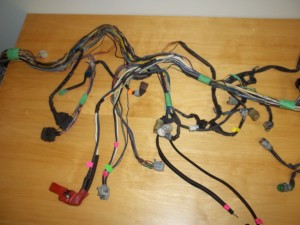
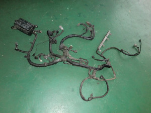
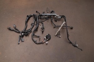
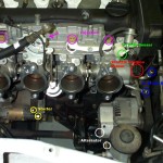
The next step is to remove the 20V wiring harness from the new engine and remove all shielding and tape. One setback I had was that my 20V harness was cut at a really bad location, so I was missing a large portion that would have really helped me trace wires. I had to work backwards and figure out what “wasn’t there” to get everything straight. Here are some images from an uncut harness that helped identify which connectors were missing.

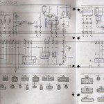
By far the best resources were the factory electrical handbook that I purchased off Ebay as well as some internet resources. In particular there is a electrical diagram from a japanese version of the silvertop FSM.


The next step is to lay both harnesses side by side and figure out what you need from each. I ended up taking parts from my old 16V harness and parts from my 20V harness, and after stripping each one of the stuff I didn’t need, I laid them together and spliced what needed to be connected. Together they formed a single new 20V harness. In this manner I was able to keep the engine bay fan and controller.


For some of the connectors I had to order new ones online (they were connected to the cut portion of the 20V harness or were damaged), fortunately if you can find the right resources, you can order “samples” of the connectors for free online. I managed to get everything I needed free of charge. After all the wiring is done, I wrapped everything up using old pieces and also some new wire protectors I ordered from Mcmaster. Also a lot of electrical tape is required. The end product was a nice shiny looking harness.

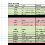
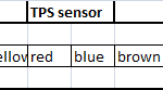
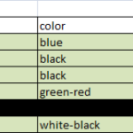
I wanted to make a tutorial video on how to do the conversion, but it became too complicated to explain using a video format. I also realized that each persons application would be slightly different, so if you decide to do it yourself, good luck. I did make an Excel helper file to identify and catalog each pin on both the silvertop engine wiring harness, as well as my 1988 MR2 body harness (automatic). You can download the complete excel sheet or just each individual connector output image. First the engine wiring harness.
-
-

-

-
-

Now the body harness.
-

-

-

-

-
-

-

-

Below are the most useful resources I had access too, these images are sourced from various areas, notably from padandwheels.com. Also a handy pin list, however I ended up making my own and finding that more useful.
-

-
-

-

-

-

-

-

-
-

-

Building a custom wiring harness for the 20V swap:
This was a close second to the hardest part of the swap. It took a long time and lots of effort to trace all the wires and make sure everything was connected properly. The first step is to remove the 16V harness from your old engine and remove all the protective shielding and tape. LABEL everything you can think of, as soon as you disconnect a connector, attach a label with a note of what it connected to. This step will help you immensely in the later stages.

The next step is to remove the 20V wiring harness from the new engine and remove all shielding and tape. One setback I had was that my 20V harness was cut at a really bad location, so I was missing a large portion that would have really helped me trace wires. I had to work backwards and figure out what “wasn’t there” to get everything straight. Here are some images from an uncut harness that helped identify which connectors were missing.


By far the best resources were the factory electrical handbook that I purchased off Ebay as well as some internet resources. In particular there is a electrical diagram from a japanese version of the silvertop FSM.


The next step is to lay both harnesses side by side and figure out what you need from each. I ended up taking parts from my old 16V harness and parts from my 20V harness, and after stripping each one of the stuff I didn’t need, I laid them together and spliced what needed to be connected. Together they formed a single new 20V harness. In this manner I was able to keep the engine bay fan and controller.


For some of the connectors I had to order new ones online (they were connected to the cut portion of the 20V harness or were damaged), fortunately if you can find the right resources, you can order “samples” of the connectors for free online. I managed to get everything I needed free of charge. After all the wiring is done, I wrapped everything up using old pieces and also some new wire protectors I ordered from Mcmaster. Also a lot of electrical tape is required. The end product was a nice shiny looking harness.

I wanted to make a tutorial video on how to do the conversion, but it became too complicated to explain using a video format. I also realized that each persons application would be slightly different, so if you decide to do it yourself, good luck. I did make an Excel helper file to identify and catalog each pin on both the silvertop engine wiring harness, as well as my 1988 MR2 body harness (automatic). You can download the complete excel sheet or just each individual connector output image. First the engine wiring harness.
Now the body harness.
Below are the most useful resources I had access too, these images are sourced from various areas, notably from padandwheels.com. Also a handy pin list, however I ended up making my own and finding that more useful.